Management of specific parameters
This paragraph illustrates the meaning of each tool parameter according to the various tool typologies.

Picture 50
In Tool Rotation it is possible to enter the tool rotation sense (clockwise or counter-clockwise). This part is the same for every tool, except for multiple drilling tools.
 Drillers
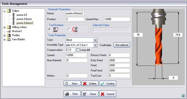
Picture 51
As regards the meaning of the Position, Max Rotation entries go back to paragraph 7.2.2. General Parameters and profile management.

The voice Type is always visualized and it specifies the type of utensil. For instance for the workmanship of perforation an utensil can be passing, blind, flared passing, reduced passing, flared blind, reduced blind. Also modifying such value the sketch of the utensil (on the right of the dialogue) it will suit him for the changes.

By Assembly Type the procedure for mounting the tool on the machining centre is meant. For instance if we want to mount a head on a normal tool change we will define vertical assemblage, if we mount it on an aggregate we will choose a horizontal assemblage.
Here follows the list of assembly types:
-Vertical: the tool is mounted vertically on a standard head;
-Horizontal Rot.1: the tool is mounted on the first outlet of an angular transmission;
-Horizontal Rot.2: the tool is mounted on the second outlet of an angular transmission;
-Inclinable 4 axes angular transmission: the tool is mounted on an angular transmission with a variably tilting outlet;
-Inclinable 4 axis head: the tool is mounted on an inclinable head around X or Y;
- 5 axis head: the tool is mounted on a 5 axis head;
- 5 axis head angular transmission: the tool is mounted on an angular transmission with one single outlet which is tooled on a 5 axis head in its turn;
- 5 axis head (1) angular transmission: the tool is mounted on the first outlet of the angular transmission which is tooled on a 5 axis head in its turn.
- 5 axis head (2) angular transmission: the tool is mounted on the second outlet of the angular transmission which is tooled on a 5 axis head in its turn.
- 5 axis head (3) angular transmission: the tool is mounted on the third outlet of the angular transmission which is tooled on a 5 axis head in its turn.
- 5 axis head (4) angular transmission: the tool is mounted on the fourth outlet of the angular transmission which is tooled on a 5 axis head in its turn..
-Horizontal Head: the tool is mounted a normal horizontal head;
-Rotating Horizontal Head: the tool is mounted a rotating horizontal head;
-Head of side Y: the tool is mounted on a head of side Y;
-Head from under: the tool is mounted a head from under;
- 5 axis head (2): the tool is mounted on the second outlet of the 5 axis head;
- 5 axis head (3): the tool is mounted on the third outlet of the 5 axis head;
- 5 axis head (4): the tool is mounted on the fourth outlet of the 5 axis head.

This parameter indicates the radius and length corrector that will be assigned to the tool onboard the machining centre. It is essential for the correct generation and execution of the final NC code. Only one machine corrector can be assigned to each tool. In case of multi-profile tool (like “c” mill) it is possible to assign a corrector to each profile. In this case the first profile is the top one.
If the corrector is set to 0 the correction is carried out by the software and not by the Numerical Control.

By Speed the revolving speed expressed in rpm that the tool takes up at the machining stage is meant.

By Max Material the maximum quantity of the material the tool can remove at the machining stage is meant. If such a value is set to zero no controls are carried out.
This value normally corresponds with the length of the present edge on the toool.

By Recess Feed the feed expressed in mm/min or in/min taken by the tool during recess machining is meant.

By Entry Feed the feed speed expressed in mm/min or in/min that the tool takes up at the piece lead-in stage is meant.

By Feed the feed speed expressed in mm/min or in/min that the tool takes up during machining is meant.

By Final Feed the feed speed expressed in mm/min or in/min that the tool takes up at the piece output stage is meant

In the Meters field the mean value of the metres the cutting tool can cover must be entered. This parameter is essential for calculating the costs of one single piece.

In the Tool Cost field the cost of the tool must be entered. This parameter is essential for calculating the costs of one single piece.
 Milling cutters
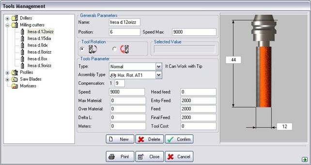
Picture 52
As regards the meaning of the Name, Position, Max Rotation and Assembly entries, go back to paragraph 7.2.2. General Parameters and profile management.

Voice Type is always visualized and it specifies the type of tool. In that case it is possibile to set the shape of rhe tool. This parameter is also important to calculate the machining because the software refers to the tool shape that can be: Normal, Bull Nose, Round, Driller, Lateral. When you modify this value the sketch of the tool (on the right of the dialogue) changes.

Assembly Type means the way the tool is mounted on the machine, for assembly type, refer to “Drilling unit”.

This parameter indicates the radius and length corrector that will be assigned to the tool onboard the machining centre. It is essential for the correct generation and execution of the final NC code. Only one machine corrector can be assigned to each tool. In case of multi-profile tool (like “c” mill) it is possible to assign a corrector to each profile. In this case the first profile is the top one. If the corrector is set to 0 the correction is carried out by the software and not by the Numerical Control.

By Speed the revolving speed expressed in rpm that the tool takes up at the machining stage is meant.

By Max Material the maximum quantity of the material the tool can remove at the machining stage is meant. If such a value is set to zero no controls are carried out.

By OverMaterial the quantity in meant, expressed in mm or inches, of the excess material thickness deliberately left on the piece; such overmaterial is applied in a radial direction. Such a value, as it can be easily understood, is very useful when some material is to be cut by using several tools and each tool must have enough material to cut for sure.

Delta L: quantity of over material in longitudinal direction.

In the Meters field the mean value of the metres the cutting tool can cover must be entered. This parameter is essential for calculating the costs of one single piece.

By Entry Feed the feed speed expressed in mm/min or in/min that the tool takes up at the piece lead-in stage is meant.

By Feed the feed speed expressed in mm/min or in/min that the tool takes up during machining is meant.

By Final Feed the feed speed expressed in mm/min or in/min that the tool takes up at the piece output stage is meant.

In the Tool Cost field the cost of the tool must be entered. This parameter is essential for calculating the costs of one single piece.
 Profiles
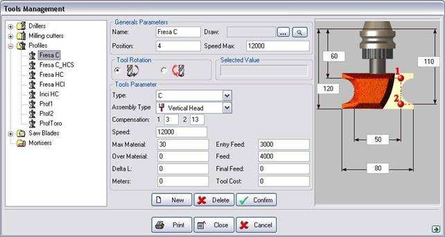
Picture 53
As regards the meaning of the Name, Position, Max Rotation and Assembly entries, go back to paragraph 7.2.2. General Parameters and profile management.

Type means the tool type/shape. The tool can be : Half CS, C, Half CI, C+Half CS, Troncated Cone, V. When you modify this value the sketch of the tool (on the right of the dialogue) changes.

By Assembly Type the procedure for mounting the tool on the machining centre is meant. Refer to “Drilling unit”.

Compensation is the number given to the tool in machine. It is essential for the correct generation and execution of the final NC code. Only one machine corrector can be assigned to each tool. In case of multi-profile tool (like “c” mill) it is possible to assign a corrector to each profile. In this case the first profile is the top one.

By Speed the revolving speed expressed in rpm that the tool takes up at the machining stage is meant.

By Max Material the maximum quantity of the material the tool can remove at the machining stage is meant. This value normally corresponds with the length of the present edge on the utensil.

By OverMaterial the quantity is meant, expressed in mm or inches, of the excess material thickness deliberately left on the piece; this overmaterial is applied in a radial direction. Such a value, as it can be easily understood, is very useful when some material is to be cut by using several tools and each tool must have enough material to cut for sure.

Delta L: quantity of over material in longitudinal direction.

In the Meters field the mean value of the metres the cutting tool can cover must be entered. This parameter is essential for calculating the costs of one single piece.

By Entry Feed the feed speed expressed in mm/min or in/min that the tool takes up at the piece lead-in stage is meant.

By Feed the feed speed expressed in mm/min or in/min that the tool takes up during machining is meant.

By Final Feed the feed speed expressed in mm/min or in/min that the tool takes up at the piece output stage is meant.

In the Tool Cost field the cost of the tool must be entered. This parameter is essential for calculating the costs of one single piece.
 Saw Blades
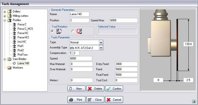
Picture 54
As regards the meaning of the Name, Position, Max Rotation and Assembly entries, go back to paragraph 7.2.2. General Parameters and profile management.

Type means the tool type/shape. When you modify this value the sketch of the tool (on the right of the dialogue) changes

By Assembly Type the procedure for mounting the tool on the machining centre is meant. Refer to “Drilling Unit”.

Compensation is the number given to the tool in machine. It is essential for the correct generation and execution of the final NC code. Only one machine corrector can be assigned to each tool. In case of multi-profile tool (like “c” mill) it is possible to assign a corrector to each profile. In this case the first profile is the top one.

By Speed the revolving speed expressed in rpm that the tool takes up at the machining stage is meant.

By Max Material the maximum quantity of the material the tool can remove at the machining stage is meant. This value normally corresponds with the length of the present edge on the utensil.

By OverMaterial the quantity in meant, expressed in mm or inches, of the excess material thickness deliberately left on the piece; such overmaterial is applied in a radial direction. Such a value, as it can be easily understood, is very useful when some material is to be cut by using several tools and each tool must have enough material to cut for sure..

By Entry Feed the feed speed expressed in mm/min or in/min that the tool takes up at the piece lead-in stage is meant.

By Feed the feed speed expressed in mm/min or in/min that the tool takes up during machining is meant.

By Final Feed the feed speed expressed in mm/min or in/min that the tool takes up at the piece output stage is meant.

In the Meters field the mean value of the metres the cutting tool can cover must be entered. This parameter is essential for calculating the costs of one single piece.

In the Tool Cost field the cost of the tool must be entered. This parameter is essential for calculating the costs of one single piece.
 Mortisers
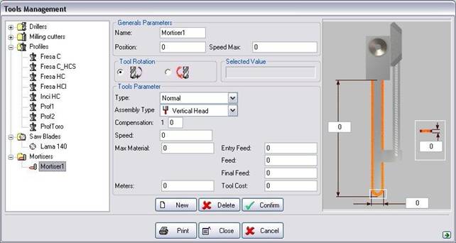
Picture 55
As regards the meaning of the Name, Position, Max Rotation and Assembly entries, go back to paragraph 7.2.2. General Parameters and profile management.

Type means the tool type/shape. When you modify this value the sketch of the tool (on the right of the dialogue) changes

By Assembly Type the procedure for mounting the tool on the machining centre is meant. Refer to “Drilling Unit”.

Compensation is the number given to the tool in machine. It is essential for the correct generation and execution of the final NC code. Only one machine corrector can be assigned to each tool. In case of multi-profile tool (like “c” mill) it is possible to assign a corrector to each profile. In this case the first profile is the top one.

By Speed the revolving speed expressed in rpm that the tool takes up at the machining stage is meant.

By Max Material the maximum quantity of the material the tool can remove at the machining stage is meant. This value normally corresponds with the length of the present edge on the utensil.

In the Meters field the mean value of the metres the cutting tool can cover must be entered. This parameter is essential for calculating the costs of one single piece.

By Entry Feed the feed speed expressed in mm/min or in/min that the tool takes up at the piece lead-in stage is meant.

By Feed the feed speed expressed in mm/min or in/min that the tool takes up during machining is meant.

By Final Feed the feed speed expressed in mm/min or in/min that the tool takes up at the piece output stage is meant.

In the Tool Cost field the cost of the tool must be entered. This parameter is essential for calculating the costs of one single piece.
Créé avec HelpNDoc Personal Edition: Produire des livres EPub gratuitement
