Engraving machining with milling cutter
By milling cutter engraving a machining carried out with the tool nose on the piece is meant.

Picture 207
N.B…By correction the position taken by the tool is meant, with respect to the piece profile during the machining phase. By profile the line displayed in the graphics area is meant instead; this line indicates the geometry that is to be machined.
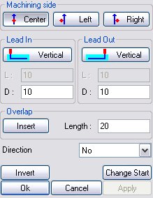
The dialog box is made up of the following sections:
Work side
 When the tool is centred with respect to the profile.
 When the tool position is on the left of the profile.
 When the tool position is on the right of the profile.
Lead in/Lead out
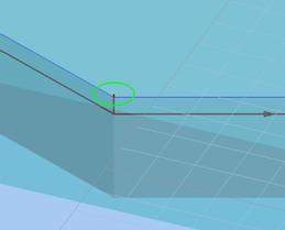
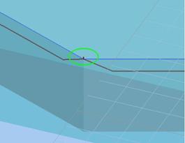
To carry out the various machining operations and the various passes, the tool needs a lead-in point (Lead-In) and a lead-out point (Lead-Out); they are displayed in the graphics area with the following representations:
 Lead in
 Lead out
Various types of lead-ins and lead-outs can be distinguished; they can be selected according to the defined machining. Selecting one lead-in or lead-out type takes place by pressing the homonymous button and by choosing the lead-in/lead-out type from the following dialog box:
 La geometria di attacco e uscita dell'utensile è perpendicolare al grezzo da lavorare.

Picture 208
 La geometria di attacco e uscita dell'utensile tasca avviene in modo obliquo rispetto al grezzo. L’ingresso obliquo viene eseguito in ingresso sulla lunghezza specificata nella casella In
 e in uscita sulla lunghezza specificata nella casella Out.

Picture 209
Overlapping

Picture 210
The overlap field enables overlapping the lead-in point and the lead-out point of the machining, or deleting an existing overlapping, if need be. It is possible to insert the overlapping only in the presence of closed paths and in tangent mode.
Now the buttons that complete the dialog box prompted by the profiling machining will be analyzed:
 By selecting this button the piece lead-in position will become the lead-out position and vice versa, that is the positions are reversed, as the command name implies.
 By pressing this button the machining lead-in and lead-out are shifted to another path point; a fundamental condition for enabling and disabling the function is that the path must be CLOSED.
After pressing this command the following message appears:

The preset entity is selected with the mouse and the path lead-in will be automatically modified.
 As the name of the command implies, this command applies the functions inserted.
 With Cancel the input settings that have not been confirmed yet are eliminated. Should the parameters not be confirmed yet, pressing cancel would take back to the kit tree.
 Ok has the function of confirming the parameters inserted for a certain machining; the complete machining of all settings will therefore be displayed in the top corner of the special machining mask.
Selecting Ok after confirming a machining implies returning to the kit tree where the machining modification and clearing buttons and the box editing buttons are active.
Créé avec HelpNDoc Personal Edition: Rationalisez la création de votre documentation avec un outil de création d'aide