Milling machining
Picture 191
N.B…. By correction the position taken by the tool is meant, with respect to the piece profile during the machining phase. By profile the line displayed in the graphics area is meant instead; this line indicates the geometry that is to be machined.
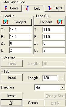
The dialog box is made up of the following sections:
Work side
 When the tool is centred with respect to the profile.
 When the tool position is on the left of the profile.
 When the tool position is on the right of the profile.
Lead-in/lead-out
To carry out the various machining operations and the various passes, the tool needs a lead-in point (Lead-In) and a lead-out point (Lead-Out); they are displayed in the graphics area with the following representations:
 Lead-in
 Lead-out
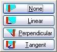
Various types of lead-ins and lead-outs can be distinguished; they can be selected according to the defined machining.
The choice of a lead-in or lead-out type is made by selecting the necessary type from the pull-down list (it is possible to make the choice by selecting the corresponding letter).
Picture 192
Hereafter reported is an example of the respective lead-in types:
None: there is no lead-in/lead-out segment that the tool must travel for starting machining; only the line is displayed, that is the entity used for entering the compensation, therefore only the L field is enabled.
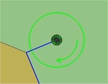
Picture 193 – Attacco Nessuna
Linear: the tool travels the correction input entity and reaches the lead-in/lead-out point by travelling along a straight path (straight line).
All the parameters are active.
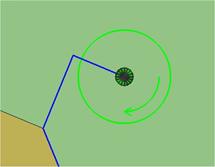
Picture 194 – Lead-in linear
Perpendicular: it carries out a profile-perpendicular lead-in; the P, Z and L parameters are active.
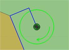
Picture 195 – Lead-in perpendicular
Tangent: it carries out a profile-tangent lead-in; all the parameters are active.
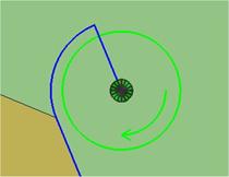
Picture 196 – Lead-in tangent
It is possible to edit the values of the T,P,Z and L parameters corresponding to:
T: distance from the lead-in point from the profile start following the profile-tangent direction;
P: distance from the lead-in point from the profile start following the profile-perpendicular direction;
Z: possible rise in Z of the lead-in;
L: length of the linear segment of the tool used for entering the compensation.
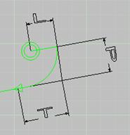
Picture 197
N.B… by “line” the compensation input entity is meant; therefore, if the user is working with a G40 compensation, no control inserted, the line does not exist and the L parameter is not active.
N.B…The program prompts some possible solutions that can be modified by assigning new parameters to the coordinates or by modifying the drawing directly in the graphics area through a drag 'n drop operation. It enables overlapping the lead-in point and the lead-out point of the machining, or to delete an existing overlapping, if need be.
N.B…. the display of the tool by means of a circle representing its diameter can vary according to the lead-in type. If a pilot hole is needed and the kit has been associated with a pilot hole, two circles will be displayed, one with the tool diameter and one with the pilot hole diameter.
If the pilot hole is drilled with the tool bit, a cross will be displayed within the circle.


Picture 198
Overlapping
It is possible to insert the overlapping only on closed paths and in tangent mode.

Picture 199
Tab
The tab is a lath of wood that holds the finished element to the blank. This lath is left to avoid machining damages on the finished element. See picture below...
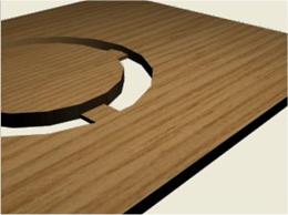
Picture 200
The dialog box below Il seguente dialogo permette di inserire tagli di sfogo in prossimità di alcuni spigoli definiti dall’utente. Nel momento in cui si seleziona tale comando appare il seguente messaggio.

Picture 201

Picture 202
This dialog allows to enter length and thickness of the Tab.
The dialog box below allows to choose the machining direction.

Picture 203
If you click the arrow on the right you get the following list where you can choose an option:
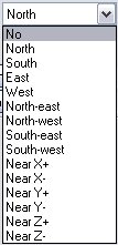
Picture 204
This dialogue shows how the tool is oriented, the options show the position of the motor referring to the machining path.
Créé avec HelpNDoc Personal Edition: Convertir des documents Word en eBooks : Un guide étape par étape avec HelpNDoc