Surface finishing machining
You can select a type of Finishing simply chosing it in the Finishing Type list or modifyin this value in the machining list. In the same tree/list it is also possible to set the approximation degree of the machining by means of the Cordal Error parameter.
Next the single types of tool will be analyzed in detail.
8.3.3.8.1.1 FlowLine
In the flowline finishing the tool follows the isoparametric lines of the surface. The resulting machining is as follows.
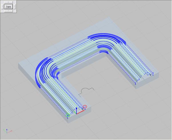
Picture 229
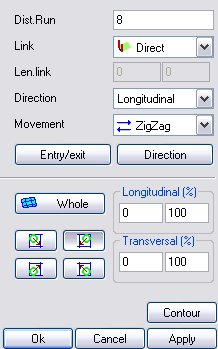
By choosing the flowline finishing, the following dialog box will appear.
Picture 230
The dialog parameters are as follows:
Pass Distance: it indicates the distance in XY between each tool pass.
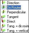
Connection: it indicates the connection type carried out between one pass and another; it is taken into account in the flowline milling cutter kit; it can be:
Picture 231
dir. Router it exits with a straight line with lenght (Connection Lenght) that has the same direction of the router and connects to the next pass in the same way;
perpendicular it exits with a straight line with lenght (Connection Lenght) that is perpendicularto the direction of the router and connects to the next pass in the same way.
tangent it exits with a straight line with length “Connection Length” that is tangent to the pass lead-out point and straight line that is tangent to the lead-in point of the following pass;
direct a geometry is inserted that traces the shape of the surface and connects the passes
tangent + router direction it exits with a straight line with length “Connection Length” that is tangent to the pass lead-out point and a straight line with length “Connection 2 length” that has the same direction of the milling cutter direction and connects to the next pass in the same way;
tangent + vertical it exits with a straight line with length « Connection Length” that is tangent to the pass lead-out point and a vertical straight line with length “Connection 2 length” and connects to the next pass in the same way.
Lead-out Length: it specifies the distance where the tool is before drawing away from the piece.
Direction: it specifies whether to machine the surface in a diagonal or longitudinal direction.
Movement: it specifies whether the generated machining is “ZigZag”- or “OneWay”-type. When "OneWay" movement and tangent connection are selected, the program automatically attempts to cover a spiral continuous path.
If the ZigZag option is selected, on completion of each pass the cutting direction is inverted; if the OneWay option is selected instead the cuttinr direction remains constant.
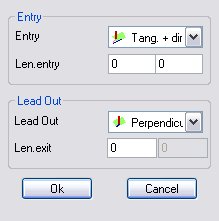
It is possible to set the parameters concerning the Entry/Exit: by selecting the homonymous key the following window appears.
Picture 232
Besides, by selecting the downward arrow it is possible to select the Lead-in/Lead-out type to be used from the pull-down list that appears; the parameters reported in such a screen page have been previously illustrated within the Kit chapter.

Picture 233
Instead by selecting the Direction button the following mask appears.
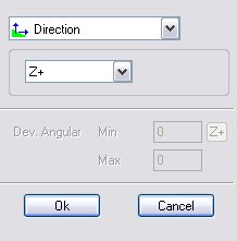
Picture 234
Inside such a dialog it is possible to enter the minimum and maximum values relating to the Angular Deviation; in particular by clicking on the  button the preset values can be selected by ticking them from the following mask.
The angular deviation refers to the axis selected in this dialog box.

Picture 235
Division
 The machining is not subdivided.
 The machining is subdivided into two parts in a longitudinal direction. The machining starts at the beginning and then reaches the middle, then it restarts from the end and reaches the middle again.
 The machining is subdivided into two parts in a longitudinal direction. The machining starts from the middle and then reaches the beginning, then it restarts from the middle and reaches the end.
 The machining is subdivided into two parts in a transversal direction. The machining starts at the beginning and then reaches the middle, then it restarts from the end and reaches the middle again.
 The machining is subdivided into two parts in a transversal direction. The machining starts from the middle and then reaches the beginning, then it restarts from the middle and reaches the end.
Start point
 With these buttons one of the four ends of the machinable surface is chosen. Besides, with the four percentage components it is possible to the delimit the range (in a longitudinal and transversal direction) of the machinable surface. In the graphics area it is possible to identify such start point thanks to the following preview.

Picture 236
8.3.3.8.1.2 Pocketing
The finishing carried out in pocketing mode machines the surface like a pocketing projected on the surface itself. The resulting machining is as follows
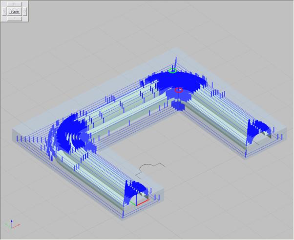
Picture 237
The dialog box relating to this finishing mode is as follows:
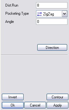
Picture 238
The parameters are as follows:
Pass Distance: it indicates the distance in XY between each tool pass.
Pocketing type: it specifies the path type to use for pocketing. It can be Spiral-, Zigzag- or OneWay-type; it is taken into account only in kits with pocketing milling cutter.
Angle: It indicates the pocketing pass angle if the pocketing is ZigZag- or SingleWay-type.
Instead by selecting the Direction button the following mask appears.
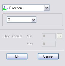
Picture 239
Inside such a dialog it is possible to enter the minimum and maximum values relating to the Angular Deviation; in particular by clicking on the  button the preset values can be selected by ticking them from the following mask.
The angular deviation refers to the axis selected in this dialog box.

Picture 240
Also with this type of machining it is possible to invert the lead-in position with the lead-out position and vice versa.
8.3.3.8.1.3 Constant Z
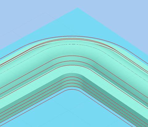
Picture 241
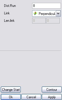
By selecting the “Constant Z” type the following dialog box appears:
Picture 242
Pass Distance: it indicates the distance in XY between each tool pass.
Connection: it indicates the connection type carried out between one pass and another; with the Constant Z machining operations it is possible to choose between

Picture 243
ConnectionLength: it indicates the connection length between two consecutive passes; in case of direct connection it is not taken into account
8.3.3.8.1.4 Projection
Picture 244
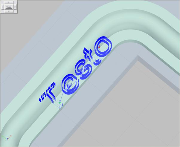
To insert a machining of this type it is necessary to start by selecting the surface on which the projection is to be applied and then associate it with a surface finishing.
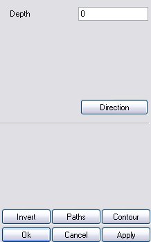
By selecting the “Projection” type the following dialog box appears:
Picture 245
By selecting the “Path” button it will be possible to choose (select) all the entities that are to be projected. During the selection a quick report of the entities that are being projected will be displayed.

Picture 246
The “Depth” parameter indicates how deep the projected path will sink into the surface. Like with all other cases it must be expressed with positive values. The entities that, if projected, would lie below the blank piece, are not projected. The "Invert" parameter enables inverting the tool cutting direction.
Créé avec HelpNDoc Personal Edition: Créer des documentations web iPhone