FlowLine
Picture 247
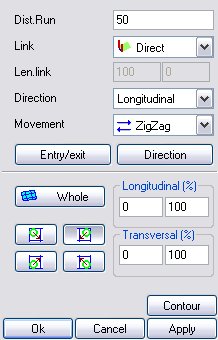
This is how the main mask of data input appears in the machining operations where a milling cutter is used. As regards the explanation of the parameters see the paragraph “properties of Surface Finishing machining". With this machining the “Direction” menu is very important as it enables defining the way in which the tool is to follow the selected surface.
8.3.3.9.1.1 Perpendicular mode
![]()
Picture 248
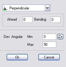
By activating this mode the software will keep the tool (compatibly with the axis strokes) always perpendicular to the selected surface.
Forward: it indicates a possible offset (in degrees) of the 5th axis direction. If for instance this parameter is set at 5 and the direction calculated by the SW for remaining perpendicular to the surface on a given point is equal to 45°, at the program generation stage, the 5th axis will be positioned on that given point at 50° instead of 45°.
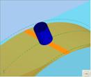
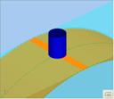
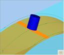
Forward=-20 Forward=0 Forward=20
Picture 249
Bend: If indicates a possible offset (in degrees) of the 4th axis direction. If for instance this parameter is set at 5 and the direction calculated by the SW for remaining perpendicular to the surface on a given point is equal to 45°, at the program generation stage, the 5th axis will be positioned on that given point at 50° instead of 45°. This parameter is often used with bevel machining, where it is necessary to “bend” with the tool slightly.
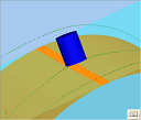
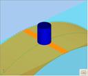
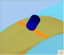
Bend=-20 Bend=0 Bend=20
Picture 250
Angular Deviation: It indicates the maximum acceptable oscillation of the 5th axis with respect to the reference axis. If for instance the above displayed figure is taken as a reference, it can be inferred that the Z+ axis has been taken as the reference axis and the “Angular Deviation” parameter is set at 90. These values will cause the 5th axis inclination during machining to oscillate between 5th axis = 0 (vertical tool, Z+) and 5th axis = 90 (horizontal tool). If the surface should contain some points the directions of which were beyond this range, the software would block the 5th axis at the next limit (0 or 90).
8.3.3.9.1.2 Side Machining Mode
![]()


Picture 251
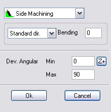
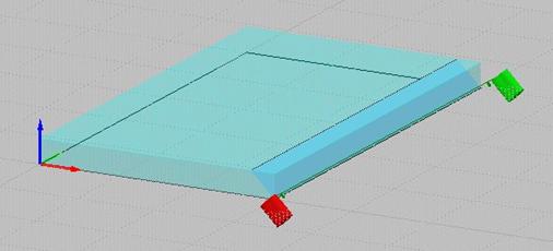
This mode enables machining a surface by keeping the tool side, not the nose, in contact with the piece.
Picture 252
Picture 253
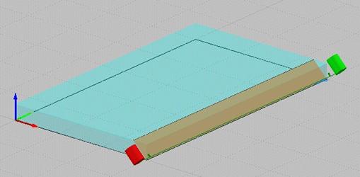
As it can be seen in the two large images above, the software enables choosing between two solutions by means of the pull-down list “First Dir.” / “Second Dir.”:
First solution: C axis = a
Second solution: C axis = a + 180
Like with the other 5 axis finishing modes, it is possible to set a “bend” value (expressed in degrees) of the C axis be means of the “Bend” parameter.
8.3.3.9.1.3 Point-through mode


![]()
Picture 254
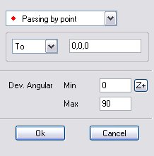
This mode allows to define a point (normally outside the raw piece) as a reference for all trhe tool’s direction:
 Picture 255
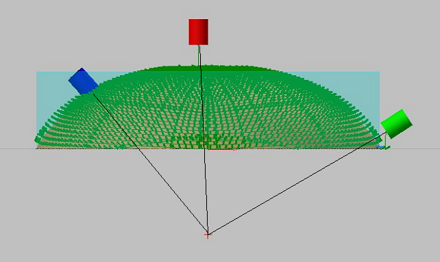
If the surface displayed in the Figure was to be machined at 5 axes but the 5th axis excursion needs to be limited, by means of the special parameter one point with coordinates {0,0,-100} must be defined (it will be highlighted by the red cross), so that the tool directions start from that point (From option) on all the surface points. As it can be easily inferred, the Z position on such a point determines one 5th axis excursion (more or less marked). If instead a concave piece rather than a convex piece should be machined, it will be advisable to activate the “sense” option.
Picture 256
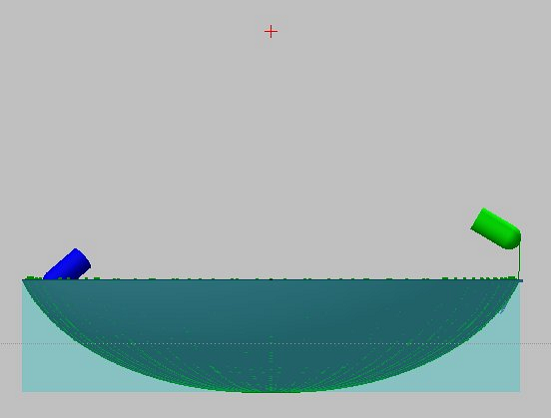
This option enables defining one point to act as a fulcrum for all tool directions, as it can be seen in the figure.
8.3.3.9.1.4 Curve-through mode

Picture 257
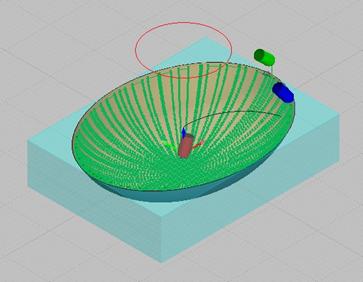
This mode is similar to the previous one (point- through mode) but instead of defining one only fulcrum/catalyser point it enables selecting a whole path.
Picture 258
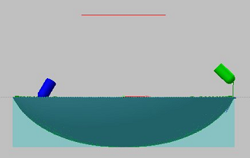
As it can be seen in the figure, a path has been drawn (highlight in red) that is external to the blank piece; during machining the fulcrum/catalyser point will move along this path. It is necessary to select the path.
Picture 259
|
Créé avec HelpNDoc Personal Edition: Révolutionnez la sortie de votre fichier d'aide CHM avec HelpNDoc