Pieces and Layers
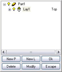
By pressing the downward arrow, the Pieces and Layers window appears.

The main tree of pieces and layers is automatically displayed. To view the subset just click on the + box of the subset that needs to be displayed, whilst for hiding it just click on the – box.
To create a new piece just press  ; to create a new layer just press the
  key. It is possible to rename the selected piece or layer by pressing the
  key; to delete it just press the
  key or Del from the keyboard.
The performed operations are confirmed with the  command which is also used for quitting the mask, similarly to the
  command.

Picture 93
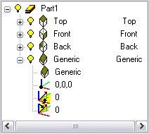
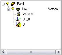
Each layer is automatically assigned one plane and a reference origin which can be one of the six canonical planes or a vertical plane, generic, right recess and left recess. Associating one layer with a plane means that all the entities belonging to this layer are automatically located on the plane that is associated with it. The properties of the plane associated with the layer can be modified by simply double clicking on the property.

Picture 94
The properties are as follows:
Plane: it is the plane type, which can be a “canonical” plane (Upper, Lower, Right, Left, Front, Back) or a “generic” plane (Vertical, Generic, Right Recess, Left Recess or 3-point-Plane).
•???? Origin: it is the position of the 0,0,0 plane point with respect to the project origin. If for instance this origin of 10 mm must be translated in X, just enter the value 10,0,0 in this field; for inputting data a mouse-defined point can also be used.
•???? Angle: it is available only for vertical and generic planes; it indicates the angle that the X axis of the plane forms with the global reference.
•???? Second Angle: it is available only for generic planes; it indicates the angle that the Y axis of the plane forms with the global reference. Therefore it enables creating oblique planes or vertical planes in case this value is set to 90 degrees.
•????? Third Angle: it is available only for generic planes; it indicates the rotation angle of the local plane around its Z.
•??? 3-point-Plane: Defining this type of plane requires inserting three points; the snap points can also be used. A generic plane will be created where the origin coincides with the first point, the X axis links the first and the second point and the Y axis is determined by the third point. The Z axis of the plane will be orthogonal to the plane passing through the three points.
The recess reference plane is a generic plane the inclination angle of which is the typical inclined recess angle, that is 5mm/m.
When the solid figure is created for the piece (see Build section), it is possible to modify the layer and piece properties interactively by simply clicking on the solid faces. If a piece has been selected and then one solid face is clicked, one layer with the reference positioned on the solid face will be automatically created. If a layer has been selected in the dialog box and then one solid face is clicked, the layer whose reference is positioned on the solid face will be made current. Finally if a layer property has been selected and then one solid face is clicked, one layer reference will be positioned on the solid face. Such an operation can be carried out also on an existing generic surface.
To select the current layer just double click on it or press Ok when it is selected. The grid will be positioned on the layer automatically and it will be possible to continue to draw on it. Each layer (except for the current one) can be easily hidden by clicking on the bulb alongside it until it gets dimmed. If instead a hidden layer is to be made visible, just carry out the reverse operation, that is, click on the bulb alongside the layer until is becomes yellow. The same operation can be performed with the pieces.
Créé avec HelpNDoc Personal Edition: Générer des livres électroniques EPub facilement